VR Lens Distortion and Stereoscopic Rendering in OpenGL
Introduction
Earlier this year, some classmates and I teamed up to build and program our own VR headset, along with a VR Minecraft clone written entirely in C. 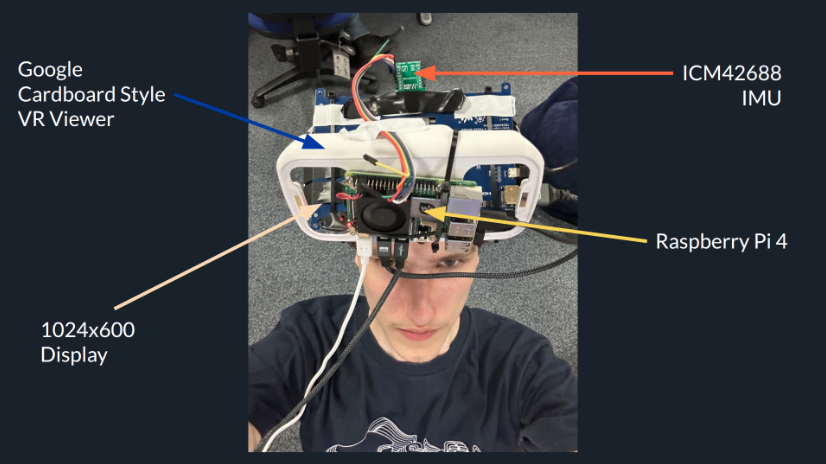 Although there were many crazy engineering feats involved in putting this all together, this post will only cover a tiny fraction of the process: how to modify your existing 3D rendering pipeline to add support for VR goggles.
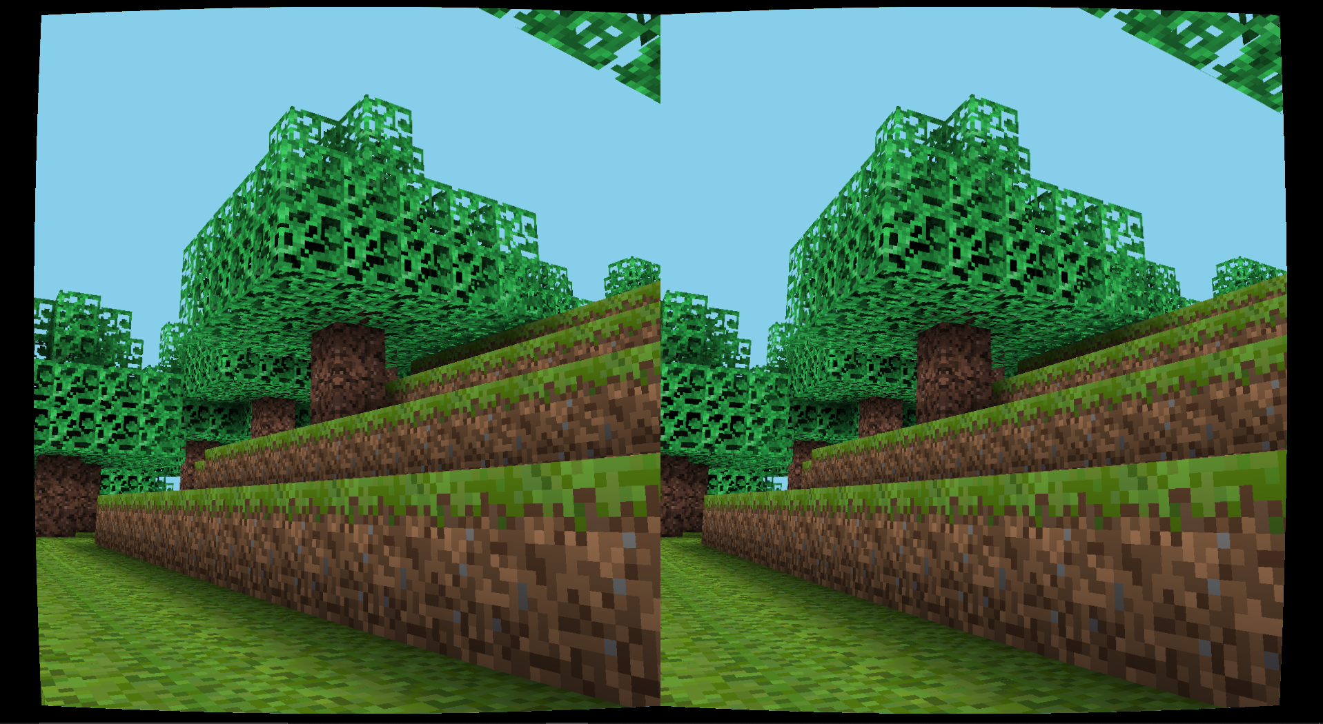
Although I’ll be going into OpenGL specifics, you should still be able to follow along if your project uses a different rendering API.
If you want to see the full source code or learn more about the VR headset project, feel free to check it out on Github!
Stereoscopic Rendering Setup
Overview
The first step is to implement stereoscopic rendering without any lens distortion. This is where we create depth perception by rendering two separate images, one for the left eye and one for the right eye. The only difference between the two images is that the camera is slightly offset by “eye distance”. Finding the right eye-distance value required some trial and error until we found one we were happy with.
To do this in OpenGL we can create two frame buffers, one for each eye, with each one containing a render buffer and a texture colour buffer. When it’s time to draw: we first move the camera slightly to the left (to be in front of the left eye), bind the left eye’s frame buffer and draw the world. This is then repeated for the right eye.
To actually display both images, we’ll use a new shader program. The only thing we’re going to draw now is a simple quad that covers the entire viewport. If we bind both texture colour buffers as active textures whilst doing this, within the fragment shader we can sample the left eye texture if the pixel coordinate is on the left half of the screen, and sample the right eye texture if the pixel coordinate is on the right half of the screen.
It may sound like a lot but I promise it’s not hard at all to actually implement!
Implementation in C and OpenGL
Our implementation begins with a post processing struct that stores all the necessary things we need for VR post processing, such as the left/right frame buffers and the post processing shader.
1
2
3
4
5
6
7
8
9
10
11
12
13
14
15
typedef struct {
    GLuint framebuffer;
    GLuint textureColorbuffer;
    GLuint rbo;
} postProcess_buffer_t;

typedef struct {
    GLuint vao;
    GLuint vbo;
    postProcess_buffer_t leftFramebuffer;
    postProcess_buffer_t rightFramebuffer;
    int buffer_width;
    int buffer_height;
    GLuint program;
} postProcess_t;
When we initialise our post processing struct, we must make sure the frame buffers are half the width of the viewport width.
1
2
3
4
5
6
7
8
9
10
11
12
/*
    Initialises everything needed to enable post-processing (shader, frame buffer etc.)
*/
void postProcess_init(postProcess_t *postProcess, GLuint shaderProgram, int width, int height) {
    postProcess->program = shaderProgram;
    postProcess->buffer_width = width / 2;
    postProcess->buffer_height = height;
    postProcess_initFramebuffer(&postProcess->leftFramebuffer, width / 2, height);
    postProcess_initFramebuffer(&postProcess->rightFramebuffer, width / 2, height);
    glBindFramebuffer(GL_FRAMEBUFFER, 0);
    postProcess_initVertices(postProcess);
}
Here’s how each frame buffer is initialised.
1
2
3
4
5
6
7
8
9
10
11
12
13
14
15
16
17
18
19
20
21
22
23
/*
    creates a frame buffer object, binding a texture colour buffer and a render buffer to it
*/
static void postProcess_initFramebuffer(postProcess_buffer_t *renderbuffer, int width, int height) {
    glGenFramebuffers(1, &renderbuffer->framebuffer);
    glBindFramebuffer(GL_FRAMEBUFFER, renderbuffer->framebuffer);

    glGenTextures(1, &renderbuffer->textureColorbuffer);
    glBindTexture(GL_TEXTURE_2D, renderbuffer->textureColorbuffer);
    glTexImage2D(GL_TEXTURE_2D, 0, GL_RGB, width, height, 0, GL_RGB, GL_UNSIGNED_BYTE, NULL);
    glTexParameteri(GL_TEXTURE_2D, GL_TEXTURE_MIN_FILTER, GL_LINEAR);
    glTexParameteri(GL_TEXTURE_2D, GL_TEXTURE_MAG_FILTER, GL_LINEAR);
    glFramebufferTexture2D(GL_FRAMEBUFFER, GL_COLOR_ATTACHMENT0, GL_TEXTURE_2D, renderbuffer->textureColorbuffer, 0);

    glGenRenderbuffers(1, &renderbuffer->rbo);
    glBindRenderbuffer(GL_RENDERBUFFER, renderbuffer->rbo);
    glRenderbufferStorage(GL_RENDERBUFFER, GL_DEPTH24_STENCIL8, width, height);
    glFramebufferRenderbuffer(GL_FRAMEBUFFER, GL_DEPTH_STENCIL_ATTACHMENT, GL_RENDERBUFFER, renderbuffer->rbo);
    if (glCheckFramebufferStatus(GL_FRAMEBUFFER) != GL_FRAMEBUFFER_COMPLETE) {
        LOG_ERROR("Failed to create framebuffer: %x", glCheckFramebufferStatus(GL_FRAMEBUFFER));
    }
    glBindFramebuffer(GL_FRAMEBUFFER, 0);
}
Now when we draw, we just have to bind each frame buffer and offset the camera position. Something to remember is you must update your projection matrix to use the new halved aspect ratio when rendering to each frame buffer.
1
2
3
4
5
6
7
8
9
10
11
12
13
14
15
16
17
18
19
static void render_with_postprocessing(world_t *world, camera_t *camera, const player_t *player) {
    glViewport(0, 0, postProcess.buffer_width, postProcess.buffer_height);

    postProcess_bindBuffer(&postProcess.leftFramebuffer);
    glClearColor(135.f/255.f, 206.f/255.f, 235.f/255.f, 1.0f);
    glClear(GL_COLOR_BUFFER_BIT | GL_DEPTH_BUFFER_BIT);
    camera_translateX(camera, -EYE_OFFSET);
    render_world(world, camera);

    postProcess_bindBuffer(&postProcess.rightFramebuffer);
    glClearColor(135.f/255.f, 206.f/255.f, 235.f/255.f, 1.0f);
    glClear(GL_COLOR_BUFFER_BIT | GL_DEPTH_BUFFER_BIT);
    camera_translateX(camera, 2*EYE_OFFSET);
    render_world(world, camera);

    glViewport(0, 0, width, height);
    postProcess_draw(&postProcess); // actually puts both textures together to render final image
    camera_translateX(camera, -EYE_OFFSET);
}
The postProcess_draw function is what actually renders the final image, which looks like this:
1
2
3
4
5
6
7
8
9
10
11
12
13
14
15
16
17
18
19
20
/*
   Uses the two frame buffers to apply the post-processing shader to them
*/
void postProcess_draw(postProcess_t *postProcess) {
    glBindFramebuffer(GL_FRAMEBUFFER, 0);
    glDisable(GL_DEPTH_TEST);
    glClearColor(1.0f, 1.0f, 1.0f, 1.0f);
    glClear(GL_COLOR_BUFFER_BIT);
    glPolygonMode(GL_FRONT_AND_BACK, GL_FILL);
    glUseProgram(postProcess->program);
    glBindVertexArray(postProcess->vao);
    glActiveTexture(GL_TEXTURE0);
    glBindTexture(GL_TEXTURE_2D, postProcess->leftFramebuffer.textureColorbuffer);
    glActiveTexture(GL_TEXTURE1);
    glBindTexture(GL_TEXTURE_2D, postProcess->rightFramebuffer.textureColorbuffer);
    glUniform1i(glGetUniformLocation(postProcess->program, "leftTexture"), 0);
    glUniform1i(glGetUniformLocation(postProcess->program, "rightTexture"), 1);

    glDrawArrays(GL_TRIANGLES, 0, 12);
}
Lastly, here’s the fragment shader used in the post-processing shader program.
1
2
3
4
5
6
7
8
9
10
11
12
13
14
15
#version 140

out vec4 FragColor;
in vec2 TexCoords;
uniform sampler2D leftTexture;
uniform sampler2D rightTexture;

void main()
{
    if (TexCoords.x >= 0.5) {
        FragColor = texture(rightTexture, vec2(2 * (TexCoords.x - 0.5), TexCoords.y));
    } else {
        FragColor = texture(leftTexture, vec2(2 * TexCoords.x, TexCoords.y));
    }
}
Putting everything together, we achieve stereoscopic rendering! 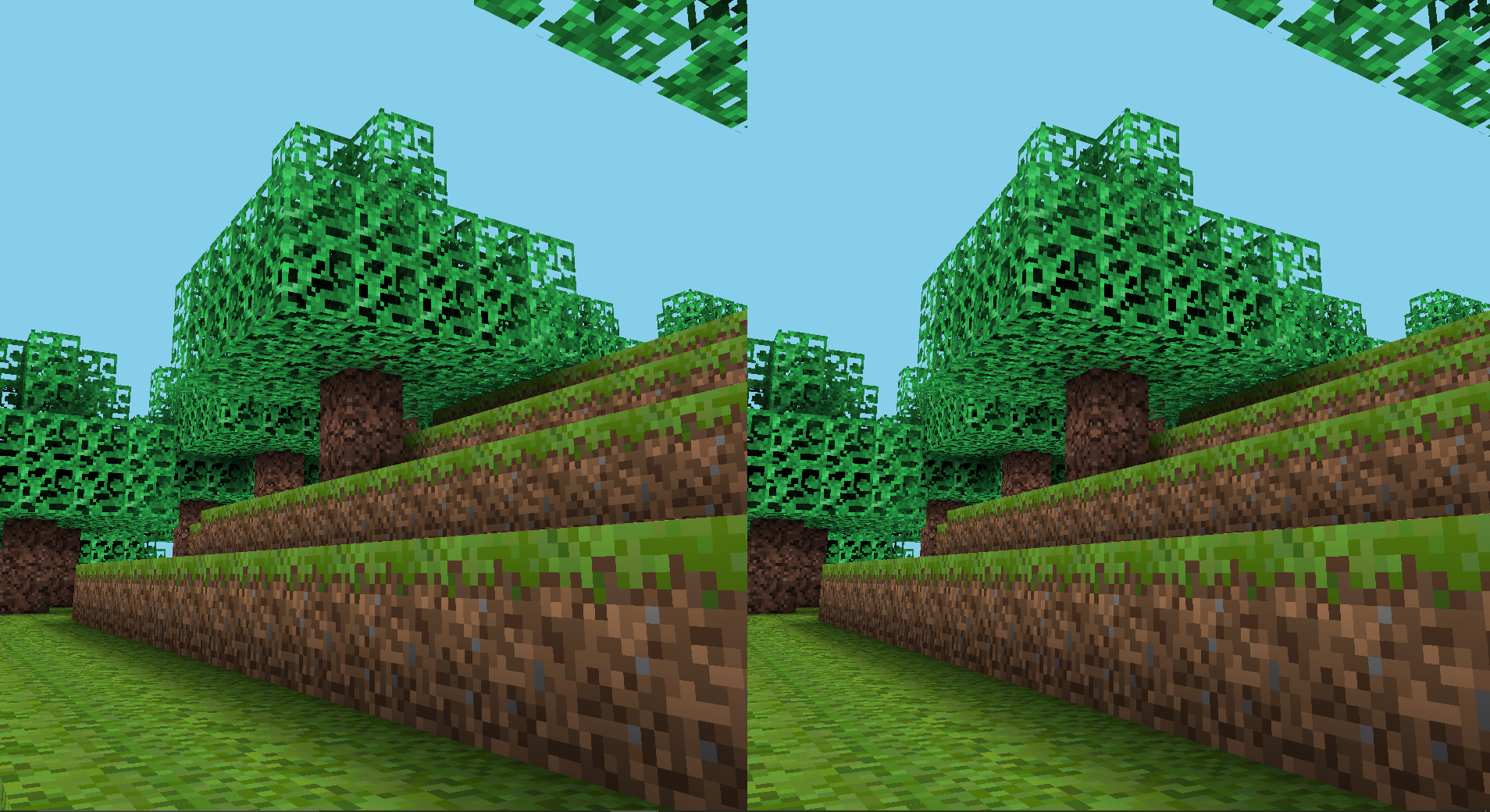
VR Lens Distortion
Overview
The only issue now with the current setup is that the lenses within the headset slightly distort the display - akin to the pincushion distortion below. To counteract this, we apply a pre-distortion within our post processing shader - so when viewed through the lenses, the optical distortion and pre-distortion cancel out, resulting in a correct-looking image.
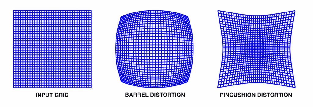 Image source: https://learnopencv.com/understanding-lens-distortion/
We can implement this by making some modifications to the fragment shader we used to sample the left and right textures and apply a barrel distortion to alter the texture coordinate used for sampling.
Barrel Distortion
Given an output pixel coordinate, we want to find the texture coordinate to sample the original texture with such that repeating this for every output pixel produces a radial distortion effect.
If you imagine the barrel distortion image above as our resulting display, something you might be able to figure out is that two pixels that are close to eachother in the centre share a much closer texture coordinate in the original input than two pixels that are close to eachother near the edges.
A simple way of replicating this starts with normalising our output coordinate to be in the range [-1, 1] with the point (0, 0) being the centre and let the radius of the normalised vector from the centre be r. We distort this r outward to a new r' with the simple cubic r' = r * (1 + k * r^2) for some k > 0. We can then sample the texture coordinate that corresponds to the new point with radius r'.
The value of k here is the distortion strength. For larger k, the distorted radius becomes much larger than the original radius - hence producing a greater distortion.
Playing around with higher order polynomials can give you a better fit for your lenses, however something to be aware of is that this polynomial should not have a constant term unless you want some funny graphics.
Implementation
Here is how the distortion for each image is calculated, using the same formula as above. The distortion strength is a uniform to allow for easier tuning.
1
2
3
4
5
6
7
8
9
10
11
12
13
14
15
16
17
18
19
20
uniform float distortionStrength;

vec2 distortEye(vec2 inTexCoords) {
    vec2 normalizedCoords = inTexCoords * 2.0 - 1.0;

    float r = length(normalizedCoords);

    float r_distorted = r * (1.0 + distortionStrength * r * r);

    vec2 distortedCoords;
    if (r_distorted > 0.001) {
        distortedCoords = normalizedCoords * (r_distorted / r);
    }
    else {
        distortedCoords = normalizedCoords;
    }

    vec2 finalTexCoords = (distortedCoords + 1.0) / 2.0;
    return finalTexCoords;
}
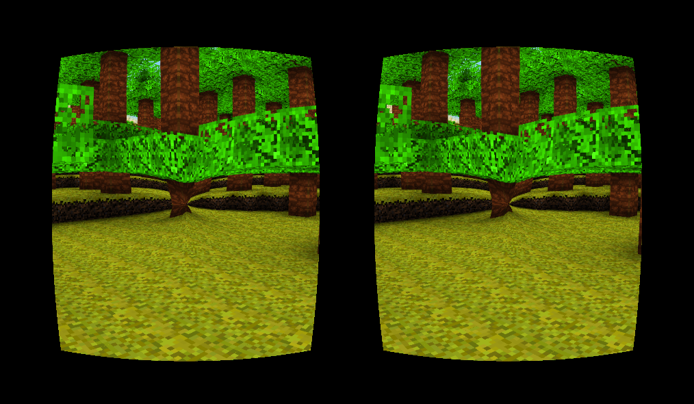
When using the texture coordinates computed by this function, we need to check if they fall outside the valid [0, 1] range - if so then we just set the pixel to black. We also have uniforms to control the centre and scale of the images produced. If you want further control you could even have different uniforms for each individual eye.
1
2
3
4
5
6
7
8
9
10
11
12
13
14
15
16
17
18
19
20
21
22
23
24
25
26
27
28
29
30
31
32
// will be between 0 and 1, representing the center of the image produced.
uniform float centerX;
uniform float centerY;

uniform float scale;

void main()
{
    if (TexCoords.x >= 0.5) {
        vec2 outTexCoords = distortEye(vec2(2 * (TexCoords.x + (centerX - 0.5) - 0.5) * scale, (TexCoords.y + centerY - 0.5) * scale));
        if (outTexCoords.x > 1.0 || outTexCoords.x < 0.0 ||
            outTexCoords.y > 1.0 || outTexCoords.y < 0.0)
        {
            FragColor = vec4(0.0, 0.0, 0.0, 1.0);
        }
        else
        {
            FragColor = texture(rightTexture, outTexCoords);
        }
    } else {
        vec2 outTexCoords = distortEye(vec2((2 * (TexCoords.x - (centerX - 0.5)) * scale), (TexCoords.y + centerY - 0.5) * scale));
        if (outTexCoords.x > 1.0 || outTexCoords.x < 0.0 ||
            outTexCoords.y > 1.0 || outTexCoords.y < 0.0)
        {
            FragColor = vec4(0.0, 0.0, 0.0, 1.0);
        }
        else
        {
            FragColor = texture(leftTexture, outTexCoords);
        }
    }
}
Thanks for reading! Once again the full source code can be found here.